
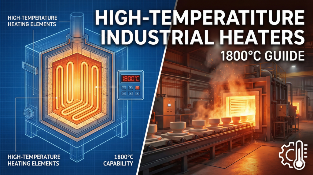
Standard thermal processing no longer meets the demands of modern manufacturing. Consequently, industries are pushing deeper into the extreme thermal spectrum. High-tech processes—from sintering aerospace ceramics to melting specialized optical glass—require sustained, precise, and uniform heat. Furthermore, this heat must far exceed the melting points of standard metals.
When your process requires operating temperatures approaching 1800°C, traditional engineering paradigms collapse. The metallic alloys that dominate lower-temperature manufacturing will literally liquefy. Moreover, the radiant tubes protecting standard heaters will melt into slag. At these extreme thresholds, thermal processing ceases to be about simply applying voltage to a wire. Instead, it becomes an exercise in advanced material science and refractory physics.
This comprehensive guide dissects the engineering, metallurgy, and operational protocols required to successfully deploy high-temperature industrial heaters. We will explore the critical transition from metallic elements to advanced electro-ceramics. Next, we will unpack the complexities of power control. Finally, we will demonstrate how you can design an ultra-high temperature furnace capable of surviving the 1800°C threshold.
1. The Physics of Extreme Thermal Processing
To understand the necessity of advanced ceramic heaters, we must first examine the absolute limits of metallic resistance heating. High-temperature industrial heaters operate on the principle of Joule heating. The equation P= I2R governs this process, converting electrical energy into thermal energy. As a process engineer, you know that managing this energy at extremes requires a delicate balancing act.
The Limits of Metallic Alloys
For decades, Nickel-Chromium (NiCr) and Iron-Chromium-Aluminum (FeCrAl) alloys have served as the workhorses of industrial furnaces. When properly engineered, a high-quality FeCrAl element operates reliably at furnace temperatures up to 1300°C to 1400°C. These elements survive by forming a protective layer of aluminum oxide (Al2O3) on their surface. Consequently, this layer halts further oxidation of the underlying metal.
However, as process temperatures breach the 1400°C mark, metallic elements face catastrophic failure modes:
Melting Point Proximity: The physical melting point of the best FeCrAl alloys is roughly 1500°C. Operating within 100 degrees of a metal’s melting point causes severe mechanical weakening. Therefore, the margin of error for temperature overshoots drops to absolute zero.
High-Temperature Creep: Gravity becomes the ultimate enemy. At extreme heat, metallic grain boundaries slip. The wire begins to stretch, sag, and eventually deform under its own weight. Ultimately, this deformation leads to short circuits against furnace walls, resulting in immediate element destruction.
Vaporization and Spalling: At temperatures exceeding 1400°C, the protective oxide layers begin to volatilize. They may also spall off during thermal cycling. This exposes the base metal to rapid, destructive oxidation.
To cross the thermal wall into the 1500°C to 1800°C range, plant engineers must abandon ductile metals entirely. They must transition to refractory compounds and electro-ceramics.
2. Silicon Carbide (SiC) Heaters: Bridging the Gap
For processes requiring temperatures between 1400°C and 1625°C, Silicon Carbide (SiC) heating elements serve as the primary bridging technology.
SiC is a non-metallic refractory material. Manufacturers extrude or cast it into solid rods, tubes, or complex spiraled geometries. Unlike metallic wire, SiC elements remain exceptionally rigid and self-supporting. Furthermore, they do not suffer from high-temperature creep.
Operating Principles and Geometries
SiC elements act relatively conductive when cold. However, they increase in resistance as they heat up to a certain point (typically around 600°C to 800°C). After reaching this point, their resistance curve stabilizes. They generate heat through direct electrical resistance, radiating massive amounts of thermal energy into the furnace chamber. Because they support themselves, they can span wide furnace chambers without requiring intricate ceramic support structures.
Managing Heating Element Aging
The most critical engineering factor when specifying SiC heaters involves understanding the element’s resistance aging process. Over its operational lifespan, the silicon carbide slowly oxidizes as it interacts with high-temperature oxygen. This interaction forms silica (SiO2):
As this silica layer grows, the electrical resistance of the element steadily increases. This aging process is not a defect; rather, it is a fundamental characteristic of the material. To maintain the same thermal power output (Watts), the power supply must gradually increase the voltage over the element’s life.
Suppose a facility installs an SiC heater on a fixed-voltage power supply. Consequently, its heat output will steadily drop over the months. Eventually, it will fail to maintain the required furnace temperature. Therefore, proper system design requires variable voltage controls to compensate for this inherent resistance drift.
3. Molybdenum Disilicide (MoSi2): The 1800°C Apex
When the manufacturing process demands the absolute pinnacle of electric heating—sustained temperatures from 1600°C up to 1800°C—Molybdenum Disilicide (MoSi2) heating elements stand as the undisputed industry standard.
MoSi2 is an intermetallic compound (a cermet). It uniquely combines the electrical conductivity of a metal with the extreme high-temperature oxidation resistance of a ceramic. Manufacturers typically forge these elements into U-shapes or W-shapes. Installers then suspend them vertically from the furnace roof to radiate heat directly into the load.
The Autoregenerative Glass Shield
The secret to Molybdenum Disilicide’s extreme temperature survival lies in its autoregenerative protective glazing. When operators heat the element above 1000°C in an oxygen-rich atmosphere, the surface silicon reacts with ambient oxygen. This reaction forms a highly dense, impermeable layer of quartz glass (SiO2).
This glass layer acts as a perfect shield. It prevents any further oxygen from penetrating the element’s core. If the glass layer cracks during operation, the element simply reacts with ambient oxygen to form a new layer of glass, literally healing itself in real-time.
Overcoming the “Pest Effect”
While these heaters thrive at 1800°C, they possess a critical, counter-intuitive vulnerability at much lower temperatures. Metallurgists call this the “Pest Effect.”
If operators run the element for extended periods in the highly specific 400°C to 600°C temperature band, it undergoes a destructive oxidation process. Instead of forming a protective glass glaze, the molybdenum oxidizes into a yellowish powder (MoO3). Consequently, the element physically disintegrates.
Unique Insight: To prevent pesting, you must program your control system to push the elements rapidly through the 400°C-600°C danger zone. Engineers designed them for extreme high heat; therefore, operators must never use them for low-temperature holding patterns.
4. The Crucial Role of Furnace Atmospheres
The atmosphere inside the furnace chamber profoundly affects the maximum operating temperature of high-temperature industrial heaters. For instance, the protective SiO2 glass layer on MoSi2 elements relies entirely on the presence of oxygen to maintain itself.
Oxidizing vs. Reducing Environments
Understanding how your process gas interacts with the heating element is just as important as the voltage you apply.
Air / Oxidizing Atmospheres: This provides the ideal environment. In ambient air, MoSi2 can safely reach its maximum rated temperature of 1800°C, while SiC can reach 1625°C.
Nitrogen (N2): At temperatures above 1500°C, nitrogen begins to react with the elements to form silicon nitride. This reaction degrades the element’s structural integrity. Therefore, engineers must carefully derate maximum temperatures when operating in pure nitrogen.
Hydrogen (H2) / Reducing Atmospheres: These environments are highly destructive. Hydrogen strips the oxygen from the SiO2 glaze, exposing the core of the element. In high-concentration hydrogen atmospheres, operators must severely limit operating temperatures (often down to 1150°C to 1300°C) to prevent rapid element consumption.
Vacuum: In a hard vacuum, the protective silica layer volatilizes entirely. Consequently, the element evaporates and contaminates the furnace load. Plant managers must specify entirely different elements (like Graphite or Tungsten) for extreme high-vacuum furnaces.
5. Advanced Power Control Systems
Designing a furnace for 1800°C is not merely about procuring the right heating elements. It requires a highly specialized, engineered electrical control architecture. Standard mechanical contactors will destroy advanced ceramic elements almost instantly.
Taming the Positive Temperature Coefficient
Both SiC and particularly MoSi2 possess steep Positive Temperature Coefficients (PTC).
When a MoSi2 element sits at room temperature, its electrical resistance is practically zero. It acts almost identically to a dead short circuit. As it heats to 1800°C, its resistance increases exponentially. If a facility attempts to apply full line voltage to a cold element, the resulting current inrush will be massive. It will instantly trip plant breakers or shatter the element via violent thermal shock.
To safely drive these elements, you must utilize phase-angle SCR control:
Phase-Angle Fired SCRs: These solid-state power controllers “chop” the AC sine wave. They deliver only a tiny fraction of total power when the element is cold. As the element heats up, the SCR gradually opens to deliver more voltage.
Current Limiting (Soft Start): Programmers must set the SCR with a strict current limit. This prevents the initial cold-start amperage from exceeding the element’s tolerances.
Step-Down Transformers: Because the operational resistance of these elements remains incredibly low, they require high current at very low voltages. Therefore, engineers pair transformers with SCRs to deliver precise voltage.
6. Mechanical Design and Installation Protocols
The physical handling and installation of ultra-high temperature elements require specific engineering protocols. Unlike highly ductile metallic wires, both SiC and MoSi2 are advanced ceramics. At room temperature, they are glass-like in their brittleness.
Suspension and Support Structures
Proper installation dictates that engineers must manage gravity, not fight it.
Vertical Suspension: Installers must hang U-shaped MoSi2 elements completely free. They cannot rest on a furnace floor or be tightly clamped at the bottom. At 1800°C, the element becomes slightly plastic. If mechanically constrained, thermal expansion will cause it to buckle and snap.
Alumina Support Straps: The element typically passes through the refractory insulation of the furnace roof. Technicians must secure it using specialized alumina-silicate holding straps. These allow for vertical expansion while isolating the electrical terminals from the extreme heat.
Braided Aluminum Straps: Installers must make electrical connections using highly flexible, braided aluminum straps. If someone bolts stiff copper busbars directly to the element terminals, the resulting mechanical vibration will snap the brittle ceramic ends.
7. Critical Industry Applications for 1800°C Heat
The ability to safely sustain 1800°C unlocks advanced manufacturing capabilities that remain fundamentally impossible with standard industrial heaters.
Sintering Advanced Technical Ceramics
The demand for high-performance materials in the aerospace and medical fields relies entirely on extreme thermal processing.
Technical Ceramics: Sintering technical ceramics like Zirconia (ZrO2) and Alumina (Al2O3) for dental prosthetics requires precise, sustained temperatures between 1500°C and 1700°C.
Refractory Metals Thermal Processing: The powder metallurgy and sintering of refractory metals require extreme thermal environments. This heat fuses metallic powders into solid, high-density components.
Glass Manufacturing: The melting of specialized optical glasses relies heavily on MoSi2 elements. Unlike aging metallic elements, MoSi2 does not flake metallic oxide scale into the melt. This ensures the glass remains optically pristine.
Semiconductor Processing: Manufacturers use high-temperature furnaces for the oxidation and diffusion processes of silicon wafers. These applications require ultra-clean heat sources that will not contaminate the cleanroom environment.
Quick Takeaways
Standard Metals Fail at 1400°C: FeCrAl and NiCr alloys melt and rapidly oxidize at extreme temperatures. This necessitates a switch to ceramics.
Silicon Carbide (SiC) up to 1625°C: These self-supporting elements increase in resistance over time. Consequently, they require variable voltage power supplies.
Molybdenum Disilicide (MoSi2) up to 1800°C: These cermet elements form a self-healing quartz glass protective layer.
Avoid the Pest Effect: Operators must ramp MoSi2 rapidly past the 400°C – 600°C range to prevent low-temperature element disintegration.
Specialized Power Required: 1800°C heaters require Phase-Angle SCRs and step-down transformers to prevent cold-start destruction.
Atmosphere is Critical: Hydrogen and Vacuum environments severely derate the maximum operating temperatures of these elements.
Conclusion
Surpassing the thermal limitations of metallic alloys represents a monumental engineering leap. The transition from 1200°C to 1800°C fundamentally changes how facilities generate and control heat.
By integrating Silicon Carbide for intermediate high-heat applications and Molybdenum Disilicide for the ultimate 1800°C threshold, manufacturing facilities can unlock new levels of material processing. However, the success of these systems hinges entirely on the quality of the elements and the precision of the electrical control architecture.
Do not let sub-standard heaters become the bottleneck of your advanced manufacturing process. When the heat is extreme, the engineering must be flawless. Are you ready to optimize your ultra-high temperature furnace? Partner with specialized manufacturers to audit your thermal architecture today.
Frequently Asked Questions (FAQs)
Q1: Can I simply replace my broken FeCrAl metallic elements with MoSi2 to increase my furnace’s maximum temperature?
No. While the MoSi2 element easily handles the heat, engineers designed your furnace’s refractory brick and power supply specifically for metallic elements. Upgrading to 1800°C requires a holistic engineering redesign of the entire furnace.
Q2: Why did my brand new MoSi2 elements turn into a yellow powder and crumble after just a few uses?
This illustrates a classic example of the “Pest Effect.” Operators ran the elements for too long in the 400°C to 600°C range. You must heat MoSi2 rapidly past 600°C to allow the protective SiO2 glass layer to form.
Q3: How do I compensate for the natural aging of Silicon Carbide (SiC) heating elements?
Because SiC oxidation causes a steady increase in electrical resistance over time, you must use a variable voltage power supply. As the element’s resistance climbs, the operator increases the voltage to maintain the required thermal output.
Q4: Do I need special hardware to install MoSi2 elements, or can I bolt them to my existing copper busbars?
You absolutely need specialized hardware. High-temperature industrial heaters made of MoSi2 are highly brittle at room temperature. Bolting them directly to rigid copper busbars will cause the elements to snap due to mechanical vibration. You must use flexible braided aluminum straps.
Q5: Are MoSi2 elements sensitive to thermal shock like other ceramics?
Surprisingly, high-quality MoSi2 elements demonstrate excellent resistance to thermal shock. Operators can heat and cool them quite rapidly. Their primary vulnerability remains mechanical shock due to their glass-like nature at ambient room temperature.
We’d love to hear from you!
Have you experienced the “Pest Effect” firsthand, or are you currently designing a system to bridge the 1800°C gap? Let us know your biggest thermal processing challenges in the comments below, and don’t forget to share this guide with your engineering team!